 ↗
BLDC Motor Control
M5 BLDC Motor Control Board
M5 · BLDC
Discuss motor matching, supply requirements and control interfaces with our engineering team.
ModelM5
Product typeBLDC motor control board
Images and specifications are from the original website. Confirm final specifications and applicable certification documents with our team.
TECHNICAL INFORMATION
Product Details
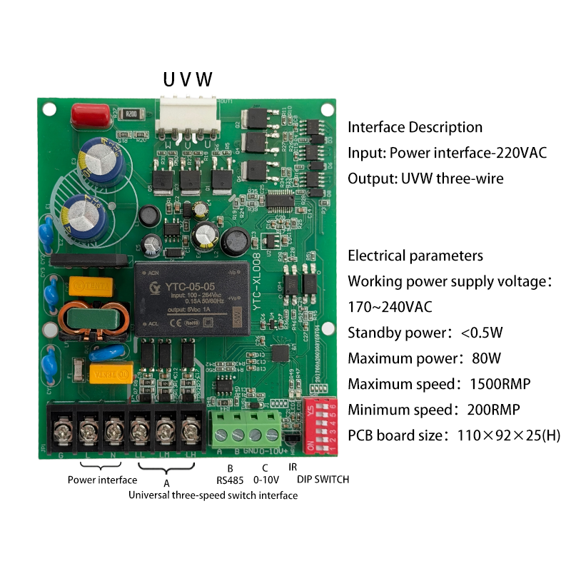
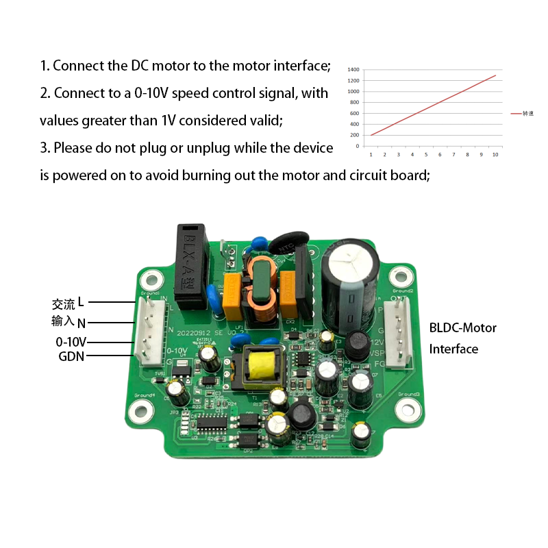
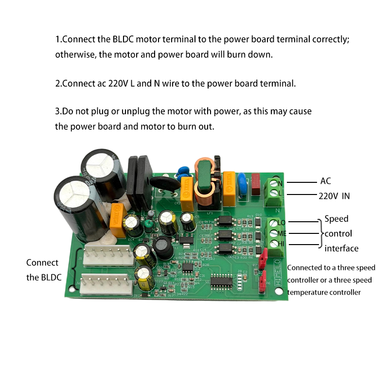
1. The power of the compatible motor should be less than 250W, with a power supply of 310V, a drive power supply of 15V, a speed regulation voltage of 0~5.5V, and a speed signal of 12 pulses per revolution. It can be optionally equipped to support the simultaneous operation of two motors. 2. It can be configured with a stepless 0~10v speed adjustment signal input, or a 3-speed switch signal input (with 0~10v signal taking priority), or connected via an RS485 port. 3. This power board features a 5-position toggle switch, allowing for a combination that provides 30-level speed control. 4. The power indicator light is continuously on, indicating that the speed is adjusted using 0-10V. When the power indicator light flashes, it indicates that the speed is adjusted using a switch signal. 1. Motor sockets and precautions A. This power board provides two DC motor sockets (indicated by the red box in the image below), which can simultaneously supply power to two DC motors with a power range of 60W to 100W. For higher power motors, it can only supply power to one motor, or the components must be changed to allow the simultaneous use of two motors. Otherwise, it may affect the normal use of the circuit board or even cause damage, and it may also fail to maintain the normal operating performance parameters of the motor. B. The wire sequence of the DC motor lead-out wire (located in the red box in the above figure) cannot be adjusted arbitrarily, otherwise it will cause damage to the motor and power board. The wiring sequence, from top to bottom, is: red (Vdc), black (Gnd), white (Vcc), yellow (Vsp), and blue (FG). The blue wire (FG) represents the speed pulse feedback output, typically used by the peripheral CPU to read speed pulses, followed by constant speed voltage regulation control, thus achieving closed-loop speed control of the motor. This can achieve a constant speed effect and is suitable for precision speed control applications.
Technical specifications
| Model | M5 |
|---|---|
| Product type | BLDC motor control board |
Contact us for electrical details, dimensions, interfaces and certification documentation not listed here.
Keep exploring
LET’S BUILD WHAT’S NEXT
Your next design starts with a conversation.
Tell us about your product, electrical requirements and application.